
<목표>
- 엔코더가 장착된 모터를 아두이노로 제어해서 사용해보자.
아두이노 공식 홈페이지에서 로터리 엔코더 사용에 대해 설명한 페이지를 우선 첨부해본다.
필요한 경우 방문을 하면 되겠다.
playground.arduino.cc/Main/RotaryEncoders/
Arduino Playground - RotaryEncoders
Reading Rotary Encoders Contents Introduction Libraries Encoder - High performance with 4X counting and very efficient interrupt routines. Uses the External Interrupt pins of the MCU. Download ClickEncoder - For encoders with button. Works on any IO-Pin (u
playground.arduino.cc
모터의 회전축에 엔코더 모듈을 부착하여 회전여부를 측정할 수 있다.
엔코더는 크게 두가지 원리가 있다.
인크리멘탈 방식과 앱솔루트 방식이 두개가 있는데, 우리가 흔히 쓰는 방식은 앱솔루트 방식이다.


인크리멘탈 방식은 위와같이 발광소자와 수광소자를 통해서 빛을 감지하는 것으로 회전수를 측정할 수 있는 것이다.
성능이 떨어지며, LED를 한개만 사용하면 회전 방향도 알 수 없다.
서로 다른 파장의 LED를 사용한다면 정확도가 증가하고 회전방향도 알 수 있다.
하지만 분해능이 확실히 떨어진다.

앱솔루트 방식은 인크리멘탈보다 정밀한 성능을 보여준다.
디스크에 슬릿이 서로다른 패턴으로 규칙적으로 있으며,
발광소자의 빛이 디스크에 나있는 구멍을 통해 검출기에 도달하면 그 신호를 이진 데이터로 변환하여 회전량을 알 수 있게 한다.
발광다이오드가 많으면 많을 수록 분해능이 더 좋다고 할 수 있으며,
패턴 비교를 통해 정방향 역방향을 알 수 있다.
앱솔루트 방식의 경우 무조건 빛으로만 신호를 검출하는 것이 아니라,
마그네틱 - 홀자기 센서를 이용해서도 회전량을 측정할 수 있다.

전자기 유도 법칙을 이용하여 코일이 있는 부분에 자석이 지나가면서 전기신호가 발생하는 것을 감지하는 것이다.

인크리멘탈 방식과 앱솔루트 방식에서 신호를 간단히 하자면 위와 같이 검출이 된다.
신호의 패턴을 통해서 정방향과 역방향으로의 회전을 감지할 수 있으며,
얼마나 많이 회전했는지도 알 수 있다.
앱솔루트 방식의 경우 모터가 가리키고 있는 방향도 패턴을 통해 알 수 있다는 것 역시 큰 장점 중 하나이다.
아두이노에서는 위와같은 신호를 통해서 회전수와 방향을 알 수 있는 것이다.
엔코더에 대해서 더 정확하게 이해하고 싶다면 아래 글을 참고하면 되겠다.
[로터리 엔코더] 엔코더의 작동 원리 및 사용 방법
모종의 일로 엔코더를 접하게 된 기회가 생겨 관련 내용을 조사해 보았는데 엔코더를 완전히 처음 접하게 되는 저의 입장에서 인터넷 상에 올라온 엔코더에 대한 정보를 이해하는데 상당히 많
elecs.tistory.com
<준비물>
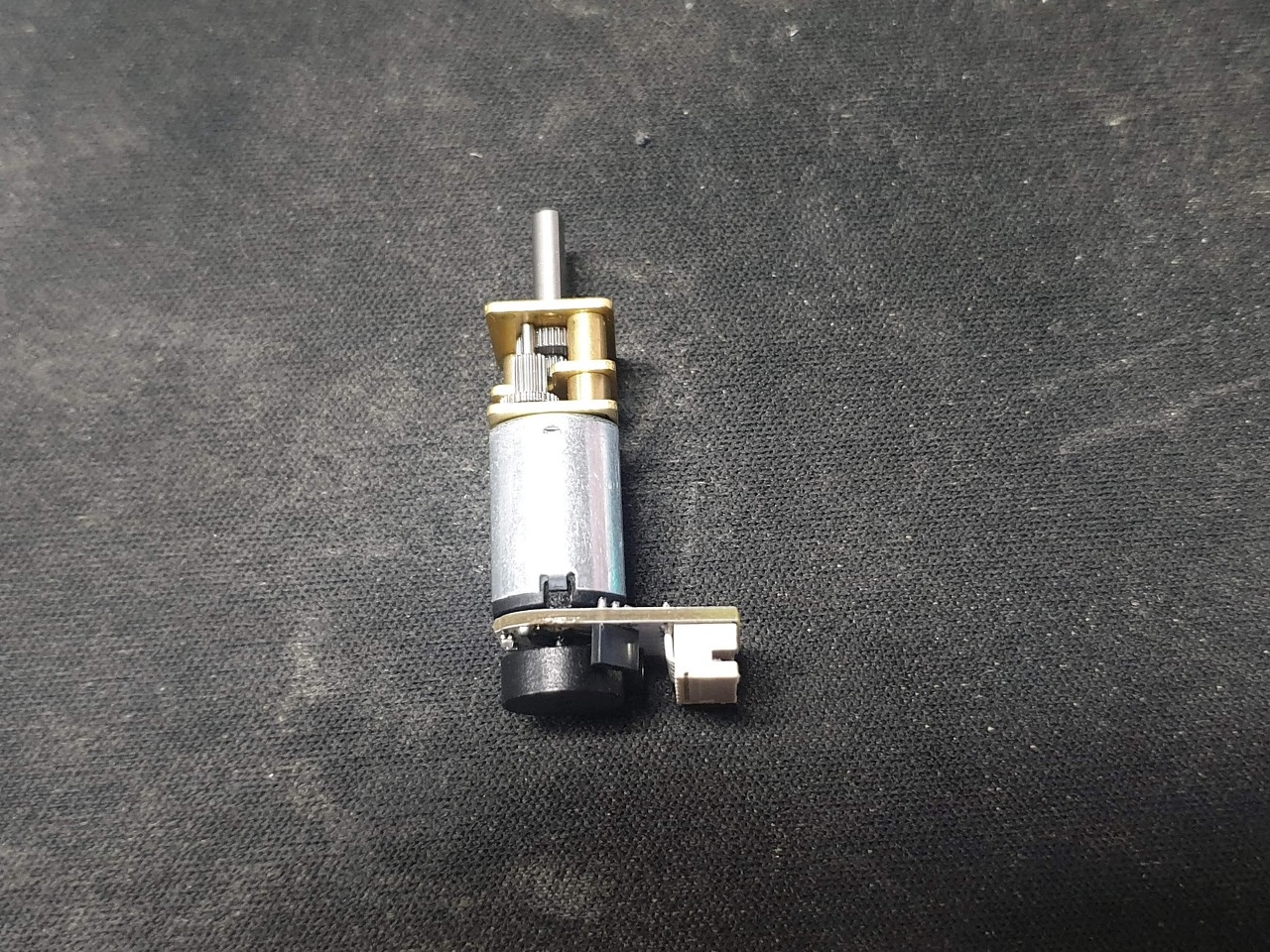
- 아두이노(우노, 나노, 메가), 엔코더 장착된 N20 모터, [모터드라이버(L298N, L9110)]
- 모터 드라이버는 있어도 되고, 없어도 되고...

C1 과 C2 는 아두이노 디지털 핀과 연결
VCC와 GND 에는 아두이노의 +5V와 GND를 연결
M1과 M2 는 모터의 양 극으로 모터드라이버에 연결하거나
아두이노의 전원단에 각각 연결해줘도 무방하다.

N20 모터의 엔코더는 홀-자기센서로 카운팅 한다.
성능은 나름 정교한 편
각도로치면 25도 정도 분해능을 가지고 있다.
int val;
int encoder0PinA = 3;
int encoder0PinB = 4;
int encoder0Pos = 0;
int encoder0PinALast = LOW;
int n = LOW;

void setup() {
  pinMode (encoder0PinA, INPUT);
  pinMode (encoder0PinB, INPUT);
  Serial.begin (9600);
}

void loop() {
  n = digitalRead(encoder0PinA);
  if ((encoder0PinALast == LOW) && (n == HIGH)) {
    if (digitalRead(encoder0PinB) == LOW) {
      encoder0Pos--;
    } else {
      encoder0Pos++;
    }
    Serial.print (encoder0Pos);
    Serial.println ("/");
  }
  encoder0PinALast = n;
}
<모터 엔코더 확인 코드>

<모터 엔코더 확인 코드 결과>
엔코더가 회전하면서 회전수가 1씩 증가하는 결과를 확인할 수 있다.
코드를 해석해보자.

n에 현재의 pinA 와 pinB의 신호를 읽어 오는데,
현재 pinA의 신호가 HIGH 이면서 이전 pinA의 신호는 LOW 일때
회전을 하는 것을 감지한 것으로 판단한다.
어느방향으로 회전하는지 판단하지 위해서 pinB의 신호를 확인하는 작업을 거친다.
pinB 에서 신호가 감지되는지 안 되는지에 따라서 회전 방향을 판단한다.

웃긴 결과를 확인할 수 있었는데
-32768 보다 더 회전하게 되면
엔코더 수치가 32767 로 시작해서 감소하게 된다.
이 현상은 엔코더 수치를 저장하는 변수가 int 이기 때문이다.
회전수가 많다면 long 변수에 저장해주는것이 좋다.
N20 모터의 경우 shaft가 1회전을 할때 엔코더는 8만큼 증가하게 된다.
만약 감속비가 1/50 이라면
N20 모터가 회전을 50번 했을 때, 최종 회전은 1번이 된다.
엔코더가 400만큼 카운트 했을 때, 1번씩 회전을 했다는 뜻이다.
위에서 사용한 코드는 테스트용도이지 실제로 엔코더를 저렇게 사용하면 안 된다.
왜냐하면 다른 센서를 사용하게 되면 측정을 제대로 못 하기 때문이다.
다른 센서의 신호를 받아오는 와중에도 모터는 회전하고 있고, 그 신호를 감지 못하고 흘려보내게 된다.
그러면 어떻게 해야 제대로 모터 엔코더를 사용할 수 있는 것일까?
이미 해답은 그전에도 다뤘었었다.
바로 입출력 인터럽트를 사용하는 것이다.
신호의 변화를 감지하는 것이 인터럽트의 기본적인 발동조건인데
엔코더의 원리가 신호의 변화이기 때문이다.
#define encoder0PinA  2
#define encoder0PinB  4

volatile long encoder0Pos = 0;

void setup() {
  pinMode(encoder0PinA, INPUT);
  //digitalWrite(encoder0PinA, HIGH);       // turn on pull-up resistor
  pinMode(encoder0PinB, INPUT);
  //digitalWrite(encoder0PinB, HIGH);       // turn on pull-up resistor

  attachInterrupt(0, doEncoder, RISING);  // encoder pin on interrupt 0 - pin 2
  Serial.begin (9600);
  Serial.println("start");                // a personal quirk
}

void loop() {
  // do some stuff here - the joy of interrupts is that they take care of themselves
}

void doEncoder() {
  /* If pinA and pinB are both high or both low, it is spinning
     forward. If they're different, it's going backward.

     For more information on speeding up this process, see
     [Reference/PortManipulation], specifically the PIND register.
  */
  if (digitalRead(encoder0PinA) == digitalRead(encoder0PinB)) {
    encoder0Pos++;
  } else {
    encoder0Pos--;
  }

  Serial.println (encoder0Pos, DEC);
}

/* See this expanded function to get a better understanding of the
   meanings of the four possible (pinA, pinB) value pairs:
*/
void doEncoder_Expanded() {
  if (digitalRead(encoder0PinA) == HIGH) {   // found a low-to-high on channel A
    if (digitalRead(encoder0PinB) == LOW) {  // check channel B to see which way
      // encoder is turning
      encoder0Pos = encoder0Pos - 1;         // CCW
    }
    else {
      encoder0Pos = encoder0Pos + 1;         // CW
    }
  }
  else                                        // found a high-to-low on channel A
  {
    if (digitalRead(encoder0PinB) == LOW) {   // check channel B to see which way
      // encoder is turning
      encoder0Pos = encoder0Pos + 1;          // CW
    }
    else {
      encoder0Pos = encoder0Pos - 1;          // CCW
    }

  }
  Serial.println (encoder0Pos, DEC);          // debug - remember to comment out
  // before final program run
  // you don't want serial slowing down your program if not needed
}
코드는 아두이노 공식 홈페이지에서 제공하는 것을 살짝만 수정하였다.
결과를 보면 아래와 같은데
이상한 점이 있다.


잘 되는 것 처럼 보이지만 역방향으로 회전하지 않았음에도 불구하고
엔코더가 잘 못 카운팅 되는 현상이 발생하는 것이다.
왜 그런 것인지 정확히 알 수 없지만
아두이노의 입출력 인터럽트는 문제가 있는 것 같다.
정확하게 안 되고, 채터링 현상이 발생하는 것 같다.

실제 신호는 왼쪽과 같아야 하지만
확대해서 보면 오른쪽과 같이 신호의 떨림에 의해서 잘못된 신호가 감지되는 것이다.
입출력 인터럽트를 많이 사용해봤지만
아두이노는 확실히 이론대로 인터럽트를 사용하기에는 부족함이 있는 것 같아 보인다.
다른 방법으로 해결해도록 하자.
코드를 조금 더 명확하게 해서 인터럽트 발생시 정확하게 카운트를 할 수 있게 해보자.
#define encoder0PinA  2
#define encoder0PinB  4

volatile long encoder0Pos = 0;

void setup() {
  pinMode(encoder0PinA, INPUT);
  //digitalWrite(encoder0PinA, HIGH);       // turn on pull-up resistor
  pinMode(encoder0PinB, INPUT);
  //digitalWrite(encoder0PinB, HIGH);       // turn on pull-up resistor

  attachInterrupt(0, Int_A, CHANGE);  // encoder pin on interrupt 0 - pin 2
  Serial.begin (115200);
  Serial.println("start");                // a personal quirk
}

void loop() {
  Serial.println(encoder0Pos);
  // do some stuff here - the joy of interrupts is that they take care of themselves
}


void Int_A()
{
  if (digitalRead(encoder0PinA) == HIGH && digitalRead(encoder0PinB) == LOW)
      encoder0Pos = encoder0Pos+1;
  else if (digitalRead(encoder0PinA) == LOW && digitalRead(encoder0PinB) == HIGH)
      encoder0Pos = encoder0Pos+1;
  else if (digitalRead(encoder0PinA) == HIGH && digitalRead(encoder0PinB) == HIGH)
      encoder0Pos = encoder0Pos-1;
  else if (digitalRead(encoder0PinA) == LOW && digitalRead(encoder0PinB) == LOW)
      encoder0Pos = encoder0Pos-1;
}

void doEncoder() {
  /* If pinA and pinB are both high or both low, it is spinning
     forward. If they're different, it's going backward.

     For more information on speeding up this process, see
     [Reference/PortManipulation], specifically the PIND register.
  */
  if (digitalRead(encoder0PinA) == digitalRead(encoder0PinB)) {
    encoder0Pos++;
  } else {
    encoder0Pos--;
  }

  Serial.println (encoder0Pos, DEC);
}

/* See this expanded function to get a better understanding of the
   meanings of the four possible (pinA, pinB) value pairs:
*/
void doEncoder_Expanded() {
  if (digitalRead(encoder0PinA) == HIGH) {   // found a low-to-high on channel A
    if (digitalRead(encoder0PinB) == LOW) {  // check channel B to see which way
      // encoder is turning
      encoder0Pos = encoder0Pos - 1;         // CCW
    }
    else {
      encoder0Pos = encoder0Pos + 1;         // CW
    }
  }
  else                                        // found a high-to-low on channel A
  {
    if (digitalRead(encoder0PinB) == LOW) {   // check channel B to see which way
      // encoder is turning
      encoder0Pos = encoder0Pos + 1;          // CW
    }
    else {
      encoder0Pos = encoder0Pos - 1;          // CCW
    }

  }
  Serial.println (encoder0Pos, DEC);          // debug - remember to comment out
  // before final program run
  // you don't want serial slowing down your program if not needed
}
카운트가 역행하지않고 정상적으로 카운트 되는 것을 확인할 수 있었다.
위의 코드를 사용하니 실제 모터의 shaft가 1회전 할 때, 14만큼 증가하는 것을 확인할 수 있었다.
이정도 코드만 있어도 엔코더가 장착된 모터를 사용하는데 전혀 지장이 없을 것이다.
※ 궁금하시거나 질문사항이 있으시면 댓글로 작성해주시면 답변해 드릴 수 있는 부분에서 친절히 답변드리겠습니다!

'코딩 > 아두이노' 카테고리의 다른 글
| 아두이노로 스마트폰에 Pushbullet을 이용하여 알림 보내기 (40) | 2021.03.25 |
|---|---|
| 아두이노로 AC 전류를 측정해보자 (AC 전류센서 [SEN0211] 사용예제) (1) | 2021.03.22 |
| nRF24L01 내장 아두이노 나노보드 최대 통신 거리 (0) | 2021.03.14 |
| 아두이노 LCD 1602 4핀(I2C제어) 디스플레이 사용하는 방법 (0) | 2021.03.14 |
| 아두이노 nRF24L01 양방향 통신 (0) | 2021.03.14 |


댓글